How to Set Up Blueprints for Modeling in Blender
Introduction
There are several ways you can create a digital model in a 3D modeling package such as Blender:
-
The first way that comes to mind is to recreate it from memory. This is a great way to model if your goal is to make a similar-looking result with your own original spin on it. This is true because humans are pretty bad at remembering details and details are crucial for making an accurate replica. Depending on the object’s complexity, this method is unlikely to yield a result that is a carbon copy of the original. Unless you have super-human memory, of course!
-
The second way is to have the object you want to recreate or its reference images in front of you. This is a better way since you would have images from various angles to help you judge proportions and details. The best case scenario would be to have the object in real life because then you would have infinite angles to look from, whereas finding that many images from different points of view online may prove challenging, and often times impossible. Say, you wanted to model a Bugatti or a Lamborghini — I don’t think many of us happen to have any of these cars lying around. Even if you do have them lying around, what if you suddenly decided to model something entirely different, such as a USS Nautilus nuclear submarine?
-
The third way is to have blueprints of the object you want to model. Blueprints are accurate drawings of object’s proportions and sizes from several orthographic points of view. This is an even better way, because in this case, we don’t have to guess the dimensions of the object, as the most crucial data we need is embedded in the blueprint.
The third way is not the best way, though, because sometimes it is not clear from orthographic views alone how a certain detail needs to look in perspective. Here is where we can construct the best way to model – by combining the third and the second ways together. In such case, we get the proportional and dimensional accuracy from the blueprint and we get perspective angles from reference images to compare our model to.
What about photogrammetry or AI?
You can create 3D models with these technologies as well, but this tutorial is about doing it the "old-fashioned" way.
Where to Get Blueprints?
You can find several places by searching the web on your search engine of choice. One of those places is The-Blueprints.com. This webpage contains both free and paid blueprints. However, to download the free ones at the maximum resolution you will have to have a registered account there. Luckily, registration is completely free.
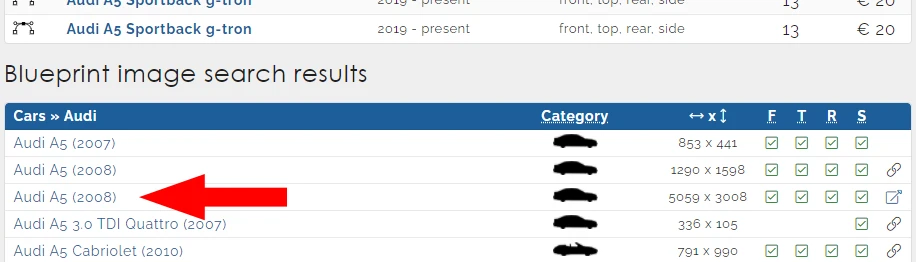
In this tutorial, I’m going to be using a 2008 Audi A5 blueprint. After registering there, enter Audi A5 into the search bar on their home page, scroll down to the Blueprint image search results and click on the Audi A5 (2008) listing shown in the image below.
Save the opened image to your drive.
Where to Get Reference Images?
There are a couple of ways I like to go about this:
- search directly on Google, or any other search engine.
- if you need an image with non-restrictive licensing, you can try to search on sites that aggregate completely-free images. Then you don’t have to worry about the licenses as much and can use the images for almost any purpose you want. Some websites like this include:
It’s still a good idea to read the usage rules on those sites anyway because there still are some restrictions on the images downloaded from there.
Importing Reference Images
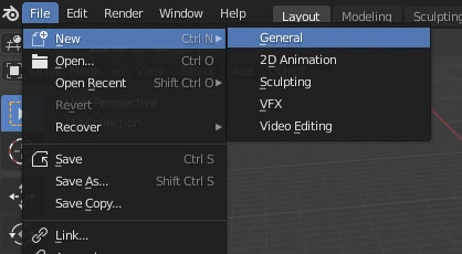
First, open Blender and create a new file by going to File > New > General or pressing Ctrl + N > General :
Select the default Camera, Light, and Cube objects in the scene by clicking the left mouse button and dragging over them. Alternatively, since we happen to need all objects in the scene deleted, you can select all objects by going to Select > All or pressing A in 3D Viewport. Delete these objects by going to Object > Delete .
Why does the mouse position matter? And what is 3D Viewport?
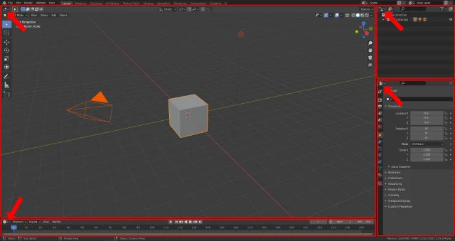
In Blender, the main screen consists of Viewports. Every viewport contains an Editor Type Selector button and can display any selected Editor Type.
In Windows operating system, for example, for any application to have focus, you need to click on it. In Blender, for a Viewport to have focus, you need to hover the mouse cursor over that Viewport.
When performing keyboard commands, Blender executes them in the context of the Viewport in focus. Different keyboard commands and even the same keyboard commands may perform different actions depending on the active Editor Type in the focused Viewport.
You can also delete selected objects by clicking X + D or X > Delete . For this to work, make sure your mouse cursor is in 3D Viewport before pressing the keys.
To add an image to Blender, either go to Add > Image or press Shift + A > Image while in 3D Viewport. You’ll notice that we have a choice between a Reference and a Background Image:
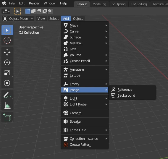
Both options will add the same Image object but with different settings.
- Reference: the Image will act like a regular textured plane. If another object is physically behind a Reference Image, the Image will obscure the object.
- Background: the Image will always be displayed in the background even if it is in front of other objects.
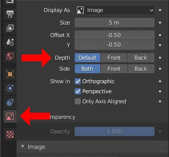
Reference Image can be converted to Background Image, and vice versa, via the Depth setting in the Object Data Properties panel on the right:
I can’t find this Object Data Properties panel.
Select the image first and the panel will appear. Different types of objects may have different panels. Therefore, what panels you see depends on what object is selected.
There are several different types of objects in Blender. Some examples include meshes, curves, images, text, etc.
Let’s finally add the blueprint to our scene. Pick Reference Image option for now and select the blueprint we downloaded earlier.
You must be puzzled right now because you can’t seem to find the downloaded blueprint in Blender File View window. You’re not hallucinating. It’s just that Blender doesn’t support GIF format and our blueprint happens to be in GIF format. You can see what graphics formats Blender supports in Blender’s documentation. To import it into Blender, we’re going to have to convert it into one of those formats. Let’s pick JPEG. You can convert the blueprint in any image editing program: Paint, Gimp, Photoshop, Affinity Photo, etc. Here is how to do it in GIMP:
- Open the blueprint in GIMP
- Go to File>Export As…
- Click on Select File Type (By Extension)
- Choose JPEG format
- Pick a location where to save the JPEG version
- Click Export
- Click another Export
- Profit!
Why can’t you just give me the blueprint instead of making me jump through all these hoops?
The-Blueprints.com forbids redistribution of their blueprints.
Once you have the JPEG version ready, import it as a Reference Image to Blender and we’ll continue in the next section.
Setting Up Blueprints
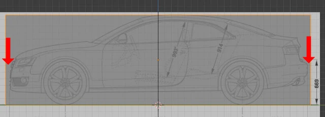
Let’s take a look at the blueprint now. Notice how the car is “photographed” from 4 different orthographic angles? We will need to align the blueprint with the same angles in Blender as well.
Setting Up Front View
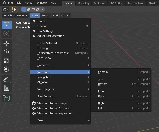
We’ll start from the front view. Press Numpad 1 while in 3D Viewport and you’ll see the view rotate into a different position.
My keyboard doesn’t have a numpad!
No worries. In 3D Viewport, go to View > Viewport.
Doing this every time may get quite tedious really fast. Luckily, there are a couple more roads that lead to Rome:
- hold the ~ (tilde) key. A pie menu will pop up. Move the mouse to the view you want to switch to and let go of the tilde key.
- hold Alt + MMB (middle mouse button) and swipe in the opposite direction you want the view to switch to.
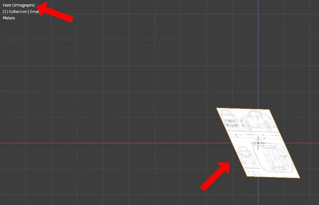
In the top left of the 3D Viewport it says which view we’re in. We’re in front view, meaning that we look at the object’s front towards the back. If you didn’t rotate the view before adding the Reference Image, you’ll notice that we have a slight problem now – our blueprint is positioned at a funny angle. We have to correct it and align it in such a way as if we were looking at the car from straight ahead.
To do that, we can rotate the blueprint until it fits our needs. Select the image and hit N while in 3D Viewport (alteratively, go to View > Sidebar ). You’ll see the Transform panel show up.
Transform panel displays the world location, rotation, and scale of the currently selected object. To mend our rotation problem, set rotation X value to 90, Y and Z to 0. The blueprint is now aligned perpendicular to our view angle, which is exactly what the doctor ordered!
Transform Tools
The next step is to center it on the grid. We can utilize the Location section of the Transform panel to move the blueprint around until the image of the front of the car is sitting on the red line (X axis) and the blue line (Z axis) cuts straight through the middle. The final result should look like this:
Alternatively, with the image selected, you can go to the Object Data Properties panel and adjust the Offset X and Y values to position the image accordingly. Either way is fine. I chose the “Transform” way because there is a quicker way to translate (i.e. change location, aka “move”) objects than to play with the sliders. There is a lot to tackle here, but this is very important, so we’ll take it step-by-step:
- With the object selected, press G (or go to Object > Transform > Move ) and move the mouse around. While in this mode, you can also use the arrow keys to translate objects by small amounts. To move them by even smaller amounts, hold Shift while moving.
- While in movement (or “Grab”) mode, we can constrain the movement to one axis by hitting their corresponding letters: X , Y , and Z . We can also exclude one axis from movement by hitting Shift + X , Y , or Z . For example, if you press Shift + Z , the object will move only along the X and Y axes. To better appreciate this behavior, use MMB (middle mouse button) to rotate the view into perspective mode.
- To cancel the “Grab”, press RMB (right mouse button). To confirm it, press the LMB (left mouse button).
The same applies to the Move tool’s close cousins: Rotate tool (R ) and Scale tool (S ).
Before moving on, take some time to play around and get comfortable with these Transform tools and hotkeys. It will make your journey with Blender much more pleasant. Once you feel ready, set up the front view to match the final result showcased in the image above and we’ll move on to setting up other view angles.
Setting Correct Scale
When we model something, we generally want to use the final model somewhere. Maybe we want to export it to a game engine, sell it online, or simply create a composition right inside Blender. In any case, odds are that our model would not be used in isolation. In our case, let’s say we wanted to use our car model in a game engine. If we were making a realistic game, our Audi would most likely be driven on roads, nearby buildings, maybe have an animation of a human getting inside the car. For the model to fit in nicely into the game environment, it has to be of correct proportions in comparison to its surroundings. After all, we don’t want the vehicle to be the size of an RC toy car when put beside a human character, or vice versa, the car to be bigger than a skyscraper in a hypothetical city building game. We have to make sure, that the model we build is going to be of correct dimension.
Measuring Distances
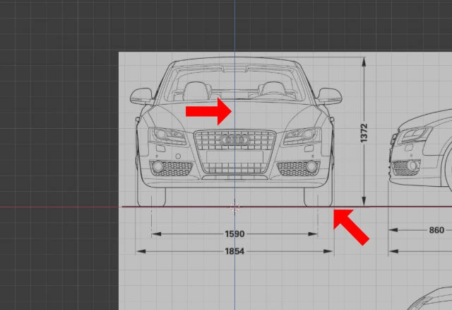
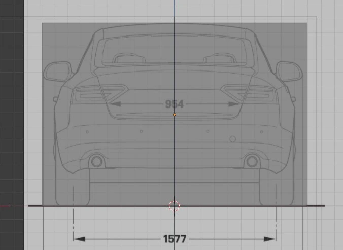
If we look at the blueprint where the back of the Audi is displayed, we can see that the width of the car from mirror to mirror should be 1981 cm. We can measure the mirror-to-mirror distance on our blueprint and see if it matches.
On the left of the 3D Viewport, there is a Toolbar with various tools. If you don’t see it, press T or go to View > Toolbar . Select the Measure tool. Alternatively, press Shift + Space > Measure . With the Measure tool active, click on the edge of one mirror and drag your mouse towards the end of the other:
The width of our car turns out to be about 1.35 meters, which is roughly 0.6 meters too narrow (don’t worry if your measurement is different). If we were to model it with these dimensions and exported without fixing them, the car would visibly stand out for being too small in the game environment. The human model would even clip through the sides and the roof of the car, which would or would not be acceptable (most likely would not) depending on your goals.
Remember when in the beginning of this tutorial I said that we “happen to need all objects deleted,” which included the Cube? Turns out I lied as we need the cube after all. It is the solution to our car-too-small problem. Fortunately, a new one can be easily added. In the 3D Viewport, press Shift + A > Mesh > Cube to add a fresh one.
In the Transform panel of the Sidebar, we can see the Dimensions section with the value for each axis:
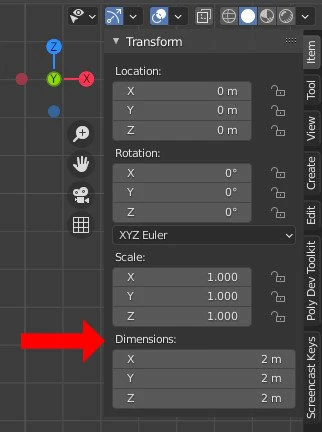
The X, Y, and Z axes corresponds with the width, height, and length of the car, respectively. We can read these values from the blueprint and set them to their respective fields in the Dimensions section. Don’t forget to convert the centimeters to meters first, or you’ll have a significantly bloated car on your hands.
Can’t we scale up/down the model at the end?
We can. It’s mostly personal preference how you like to model.
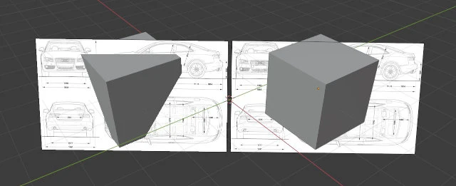
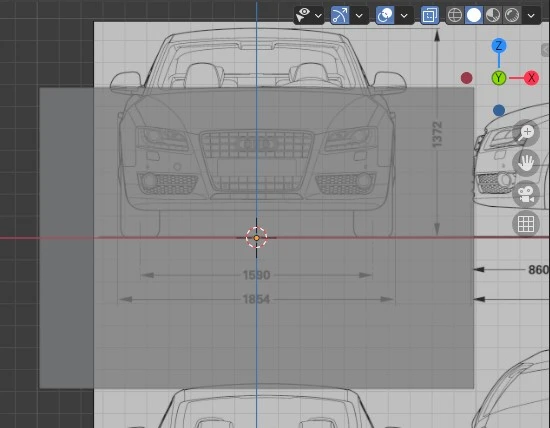
Now that we have the bounding box of the vehicle with correct dimensions, we need to scale the blueprint to fit right inside the cube. To make this process easier, let’s make the cube transparent. Press the Toggle X Ray icon as shown in the video below, or simply press Alt + Z :
Great. Now we can barely see the cube. There are a couple of options here:
- adjust the Reference Image’s opacity in the Object Data Properties panel
or
- convert the Reference Image to Background Image
To convert an image from Reference to Background, set the Depth to Back in the Object Data Properties panel:
Feel free to experiment and see what works for you best. If you want to follow along with my set-up, I have the Depth set to Back and the Opacity set to 0.5. Here is how it looks:
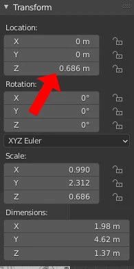
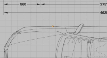
Before we proceed with aligning the car image with the box, we need to move the box up so that it sits on the X axis (red line). Since the X axis divides the box in two equal halves, we can simply set the Location value of the Z axis to the half of the Z dimension, which is 0.686 m:
Using Transform Pivot Points
If you tried to scale up the blueprint by pressing S and moving the mouse around, you would notice that it scales from its center. This center is called the Origin and is marked by a yellow dot at the center of every object:
In Blender, rotation and scaling happen around a point called the Pivot Point, which is set to Median Point by default. To make scaling up our blueprint easier, let’s change the pivot point to something else. There are several options but we’re going to be using the 3D Cursor one. Press ..
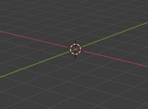
3D Cursor is the best option in our case, because of the way we have our car image set up. The 3D cursor is currently set to the world origin, which is the center of the scene where all axes intersect.
We have the car image set up so that it sits right in the middle of the world. So if we scaled the image now, it would expand in all directions from the 3D Cursor:
Adjust the scale so that no part of the car sticks out of the cube’s borders. Note that there are a couple of issues:
- there may be gaps between the sides of the cube and the mirrors. It means that the blueprint isn’t perfect. Ideally, the edges of the mirrors should be touching the sides of the cube, since we used the exact mirror-to-mirror dimension displayed on the blueprint for the width of our cube. It does not matter much though, because we’re going to be deleting the cube anyway. We’re only using it to set up the blueprints.
- the gap between the mirror and the edge is wider on one side than on the other. This also means an imperfection in the blueprint. It doesn’t matter here as well, since it is a minor difference and we will be using the mirror modifier to copy half of the model to the other side anyway.
Setting Up Side View
Remember how we had to adjust the rotation of our blueprint to match the front view? That was because we added the image in Perspective mode. This time, switch to the view we want the image to be added to (in our case, it’s Right view), then press Shift + A > Image > Reference in 3D Viewport and select the car blueprint. Notice how the image is added with correct orientation with respect to our view angle.
What do perspective and orthographic mean?
Orthographic view is an artificial way of seeing the world. We can’t observe depth while in orthographic view, because all objects are rendered as if they were at the same distance from the viewer.
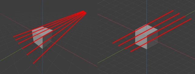
Notice how the red lines appear to get closer and closer to one another towards the distance on the left hand side of the image below. If we extended those lines further beyond, they would converge into a single point. This point is called the vanishing point.
Look at the right hand side of the below image. On the contrary to perspective view, in orthographic view, the red lines appear as dots and they go into the distance orthogonal to other lines. None of them will ever converge with one another.
You can switch between perspective and orthographic views by pressing Numpad 5 or by going to View > Perspective/Orthographic in 3D Viewport.
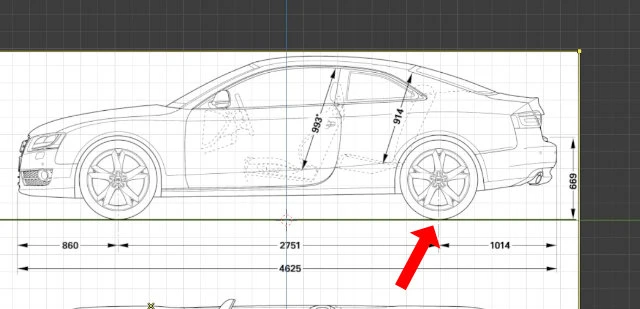
The next step is to position the side-view blueprint correctly. Position the car so that the Z axis goes roughly through the middle. Align the wheels so that the car sits on the Y axis. To achieve this, use the same techniques we used setting up the front view. The result should look somewhat like this:
To scale up the image, we can use the same scale value from the front view. Select the front view image and note the scale values in its Transform panel on the right. Mine are 1.435. Don’t worry if yours are slightly different. As long as the difference would not be visibly discernable and all blueprints align, it will be fine.
Select the side view blueprint and scale it until its scale values in the Transform panel matches those of the front view image’s. Hold Shift while scaling for fine-grained control. Alternatively, you can adjust the Size property of the image in its Object Data Properties panel instead of scaling. I chose to scale though.
Once you’re done and verify that no part of the car extends beyond the edges of the cube, you’ll notice that there may be gaps between edges of the cube and the front and back of the car:
Adjust the cube’s Y scale value until the edge of the back bumper aligns with the edge of the cube. This will help set up top view more accurately:
Shouldn’t the front bumper be matched to the cube as well?
It’s not necessary since one reference point, in our case – the back bumper, is enough. You could have chosen to align only the front bumper instead of the back bumper too, and then use the front bumper as a guide when aligning the top view within the cube. Or, you could simply not have bothered with it at all and eyeballed the gaps when aligning the top view. It doesn’t matter much how you do it. The goal is to have all sides of the car aligned to each other as accurately as possible. However, don’t obsess over it too much, because blueprints may be imperfect and it is not uncommon to be impossible to align them perfectly.
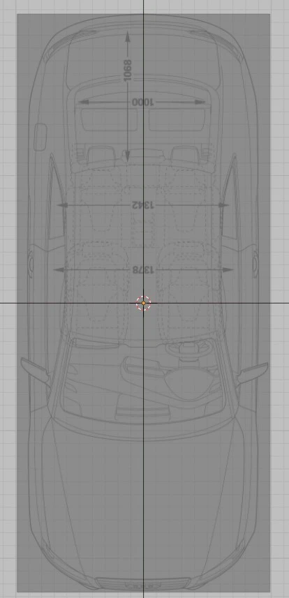
Setting Up Top and Back Views
Use what we’ve learned so far to to set up the top and back views. The results should look like this:
Once you’re finished, check all the views if they’re aligned correctly – none of the parts should be sticking out out the cube. You can delete the cube now as we won’t be needing it anymore. I’m telling the truth this time, I swear! Or you can leave it be – it’s up to you.
Cleaning Up Outliner
Outliner is an Editor Type that can be found in the top right corner of the screen:
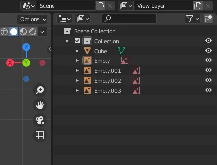
It displays a hierarchical list of objects in the current scene. We see that there is a “Cube” and 4 “Empty” objects in the scene. What are these “Empty” objects? We sure didn’t add any of those, did we? They are our Reference Images that Blender names this way when adding them. But which one of them is the front view, the back view, etc.? What if we took the cube and shaped it into a cat? Yet, its name would still be “Cube”. Hopefully, you can see how this may become problematic if we had, say, 100 different objects in the scene, all arbitrarily named. It would take ages to find what we were looking for. Therefore, it’s paramount to develop a habit of keeping your Outliner organized.
Renaming Outliner Objects
This is how I organized mine:
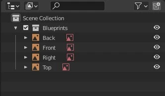
To rename an object in the Outliner, double click on it with LMB or select it and press F2 . Rename the Collection as well. Collections are containers for objects. You can create new collections by going RMB > New Collection where you want it created in the hierarchy:
As an exercise, let’s move “Cube” object into its separate collection. We can both move and create a new collection with one command: select the cube and press M From here, you can choose to create a new collection, give it a name and the cube will be moved to the new collection.
Conclusion
This wraps up the tutorial. I hope it was clear and you had a great time following it. I’d like to take a moment and summarize the key concepts to take away from this tutorial as it comes to working in Blender:
- There is more than one way to achieve the same result. For example, when setting up the front view of the blueprint, we could have created the cube first and then added the reference images and aligned them into the cube. Or, we could have skipped the whole scaling the blueprints process, including playing with the cube, and just scaled up the model once we were done modeling. The final result would have been the same either way. Keep an open mind, keep experimenting, see what works for you best.
- Keyboard shortcuts are king. Make sure you learn them and use them. Once you get more comfortable with Blender, they will speed up your workflow immensely.